TeamSwift

Home of the Suzuki mini-compacts ! Your Home for all things Suzuki Swift, Geo Metro, Holden Barina, Chevy Sprint, Pontiac Firefly, and Suzuki Cultus. TeamSwift is a technical performance oriented community!
It is currently Thu Nov 23, 2017 7:31 pm

Underbody braces, turbos and more!

All times are UTC - 5 hours


Post new topic Reply to topic  [ 72 posts ]  Go to page Previous  1, 2, 3  Next
Author Message
PostPosted: Tue Oct 20, 2009 3:40 am 
Offline
User avatar

Joined: Sat Mar 22, 2008 8:44 pm
Posts: 46
Here is the recepy for the drys sump system on my car.

I use a two stage scavenge pump. It is a Pace Products CD2000 with 1.1" rotors run @ half crank speed. I use a ordinary L-section belt and two pulleys to drive it off the crank. It runs at half the engine speed.

The oil pan has one scavenge drain at the front and one at the rear (One for each section of the scavege pump). At least AN10 swept fittings are recommended from the pan to the pump, and the one (combined oultlet) tube from the pump to the tank is AN12. The scavenge pump pumps the air/oil mixture to an oil tank where the oil is de-aired. That tank is approx 5 litres in size and it has internal plates to aid the air/oil separation. I bought it second hand so i do not know what make it is.

I use the original engine oil pump for pressure.
The engine oil pump is fed from the bottom of the oil tank. There is a threaded bung in the side of the oil pump that can be used. I removed the original oil pickup and made a plug to seal the hole by cutting the tube to the oil pickup (about 1cm length), flattening it and and welding it shut before mounting it again.

Below is afew pictures of the oil pan, and also some overview pictures of the dry sump system and the crankcase ventilation.

/Peter


Attachment:
12005-new_2009-03-02-slide1.jpg
12005-new_2009-03-02-slide1.jpg [ 52.9 KIB | Viewed 11662 times ]

Attachment:
12005-new_2009-03-02-slide2.jpg
12005-new_2009-03-02-slide2.jpg [ 32.18 KIB | Viewed 11668 times ]

Attachment:
12005-new_2009-03-02-slide3.jpg
12005-new_2009-03-02-slide3.jpg [ 97.27 KIB | Viewed 11670 times ]

Attachment:
DSC00204 (Large).JPG
DSC00204 (Large).JPG [ 149.67 KIB | Viewed 9766 times ]

Attachment:
DSC00200 (Large).JPG
DSC00200 (Large).JPG [ 125.73 KIB | Viewed 9762 times ]

Attachment:
DSC00202 (Large).JPG
DSC00202 (Large).JPG [ 120.71 KIB | Viewed 9762 times ]


Last edited by pelle17b on Sat May 21, 2011 1:00 am, edited 1 time in total.

Top
 Profile  
 
PostPosted: Tue Oct 20, 2009 4:55 pm 
Offline
User avatar

Joined: Fri Nov 28, 2003 4:21 pm
Posts: 593
Location: Durham, UK
Hi,

Thank you very much for a detailed reply.
So, two stage scavenge pump is only 1 pump. I thought it was 2 pumps used.... :oops: .

I got a spare sump so I might make one for a dry sump.
You said 5 litres tank, how much oil do you put in?
Std capacity is 4 litre and by reducing oil sump, oil will moved to tank.
Do you supply oil to turbo charger?

Cheers
Atchi


Top
 Profile  
 
PostPosted: Wed Oct 21, 2009 2:15 am 
Offline
User avatar

Joined: Sat Mar 22, 2008 8:44 pm
Posts: 46
Well it is one "pump", but with two scavenge sections bolted together and one outlet. It is modular in its design so I think you can add more scavenge sections and a pressure section too if you want. You can see the pump in the picture below.

Attachment:
P1010009.JPG
P1010009.JPG [ 122.82 KIB | Viewed 9761 times ]


Yes I supply oil to the turbo. I use one of the threaded bungs in the block above the oil filter (where the oil pressure switch is) for the turbo supply. I use a T-coupling threaded into the bung in the block. From the T i have two steel braided hoses. One to the turbo and the other to an oil pressure sensor. The oil pressure sensor (aftermarket analogue type) is mounted to the chassis to avoid fatigue problems due to vibrations. It is not good to have a lumped mass object (the sensor) mounted on long a stick (T-coupling) in a vibrating environment. Bound to break sooner or later. A sensor threaded directly into the block would probably be ok though.

I think i put in around 6 litres of oil including filter and oil cooler.

/Peter


Top
 Profile  
 
PostPosted: Wed Oct 21, 2009 3:02 am 
Offline
User avatar

Joined: Fri Nov 28, 2003 4:21 pm
Posts: 593
Location: Durham, UK
Hi Peter,

Thank you again for fast and detailed reply.
My friend was bit worried about taking oil from said part to a turbo.
He thought oil will take easier route so engine might get oil stervations. But many people woh fit turbo to G13B engine uses same method so I didn't think it will be a problem.
Would oil get that hot? I heard too cold engine oil is not good either. Perhaps, you have hot oil returning from a Turbo to deal with....
I'm thinking of a heat exchanger plate between oil filter and block to deal with extra heat created by turbo oil circulation.

I think I will start to save my pennies!

Cheers
Atchi


Top
 Profile  
 
PostPosted: Wed Oct 21, 2009 5:35 am 
Offline
User avatar

Joined: Sat Mar 22, 2008 8:44 pm
Posts: 46
My oil cooler is connected to a sandwich plate between the oil filter and the engine. The sandwich plate contains a thermostat so the oil cooler is only used when oil is hot.

I do not know how much the oil cooler is needed, but on a seven like mine there is not much space for a big radiator under the nosecone so any means to get the heat out are good i think. The oil cooler will definitely help in that.

The engine output with the turbo is roughly 50% higher than stock, so I suppose that the need for cooling is raised by roughly the same amount.

A heat exchanger plate will only help if you have enought cooling capacity in the water radiator.

/Peter


Top
 Profile  
 
PostPosted: Wed Oct 21, 2009 4:53 pm 
Offline
User avatar

Joined: Fri Nov 28, 2003 4:21 pm
Posts: 593
Location: Durham, UK
Hi Peter,

I have looked at service manual for Gti engine.
Std engine oil pump is rated 25 litre/min @ 4000rpm.
Your pump is 13.5litres/min @ 1000pump rpm. Is this mean you have 2x 13.5 litres?

I'm thinking of buying 2 bike scavenge pumps off Honda Gold wing 1200cc bike.
It might be bad idea.... but I'm looking into it.

Thank you again for your info.

Cheers
Atchi


Top
 Profile  
 
PostPosted: Thu Oct 22, 2009 3:32 am 
Offline
User avatar

Joined: Sat Mar 22, 2008 8:44 pm
Posts: 46
Pace products estimated the stock oil pump capacity to 8 l/min @1000rpm based on my measurements of the mechanical dimensions of the stock pump. This would compute to 32l/min @4000rpm (not spot on but not extremely far from 24l/min @4000 rpm).

The 8 l/min@1000rpm was used to calculate the needed size for the scavenge pump.

As a rule of thumb the scavenge capacity shall be twice the pressure pump capacity.

2 scavenge stages that each pump 13.5l/min@1000 pump rpm gives a total scavenge capacity of 13.5 l/min @ 1000 engine rpm since the pump is driven @ half the engine speed.

So Pressure pump capacity 8l/min@1000 rpm engine speed and Scavenge pump total capacity 13.5l/min @ 1000rpm engine speed.

If we use the factory pressure pump figures the pressure pump would put out 24/4 = 6 l/min@1000engine rpm so that gives a litttle more margin on the scaenge pump capacity, but still pretty close to the rule of thumb of twice the capacity.

Regarding the bike pumps i have no clue if they will work or not. Sorry.

Edit. I also measured the dimensions of the 1.6l suzuki oilpump. If my measuremetns are correct that pump flows approximately 15% more than the G13B pump. Roughly 7 litres per minute and 1000rpm.

/Peter


Last edited by pelle17b on Wed Feb 23, 2011 4:05 pm, edited 1 time in total.

Top
 Profile  
 
PostPosted: Thu Oct 22, 2009 5:19 am 
Offline
User avatar

Joined: Fri Nov 28, 2003 4:21 pm
Posts: 593
Location: Durham, UK
Hi Peter,

You have given me more than enough info.
I can't thank you enough.
I have more idea of what to do and how to do now, all thanks to you.

Cheers
Atchi


Top
 Profile  
 
PostPosted: Thu Oct 22, 2009 12:34 pm 
Offline

Joined: Thu Oct 15, 2009 3:52 pm
Posts: 9
Location: England
Cheers for this information, its a gold mine. Its going to make my eventually switch over alot easier :)


Top
 Profile  
 
PostPosted: Mon Jan 04, 2010 5:29 pm 
Offline

Joined: Thu Oct 15, 2009 3:52 pm
Posts: 9
Location: England
If anyone is still interested in the project I finally got around to fixing my website, www.joshogilvie.com

Also pelle17b do you have any more pictures of your build? I like following these kind of things :)


Top
 Profile  
 
PostPosted: Tue Jan 05, 2010 4:12 am 
Offline
User avatar

Joined: Sat Mar 22, 2008 8:44 pm
Posts: 46
I looked at your site. Nice build!

I have a few build pictures at this link: http://www.superseven.se/sevengallery/#home

/Peter


Top
 Profile  
 
PostPosted: Tue Jan 05, 2010 7:44 am 
Offline

Joined: Thu Oct 15, 2009 3:52 pm
Posts: 9
Location: England
Your fuel tank is genius, i don't think you'll be getting fuel surge... ever :P

Do you still have the CAD drawing for your exhaust flange?


Top
 Profile  
 
PostPosted: Tue Jan 05, 2010 2:57 pm 
Offline
User avatar

Joined: Sat Mar 22, 2008 8:44 pm
Posts: 46
Well, the tank is foam filled also so no fuel surge so far :-).

A disadvantage with the placement is that the Cg of the car gets a little higher due to the placement on top of the diff instead of the traditional placement behind it.

Advantages are slightly better safety since the tank is not placed in the immediate area of impact if someone should hit me from behind. It is also a lightweight and simple solution with the gravity filled catch tank compared to having a separate catch tank with an extra fuel pump and all the hoses and stuff involved.

Here is the cad file for the Exhaust flange. I think that many companies doing lasercutting will take the step format. Just let me know if you need another format.

Attachment:
Suzuki_G13B_Exhaust_Manifold_Flange.zip [34.01 KIB]
Downloaded 390 times


I have an extra flange left since I made mine. Lasercut from 10mm ordinary steel (not stainless). Price is 40USD + shipping, but I fear that including the shipping cost from sweden to US it might not be worth it compared to ordering one locally. Just send me a PM with your address if it sounds interesting and I will check the exact shipping cost.

/Peter


Top
 Profile  
 
PostPosted: Wed Jan 06, 2010 6:54 am 
Offline

Joined: Thu Oct 15, 2009 3:52 pm
Posts: 9
Location: England
Cheers peter! Thats going to save me a few hours with some calipers at the cad machine :)

I'm actually in the UK so shipping wouldn't be too bad, but I'm planning on getting one made in 316 stainless, as the whole system on mine is going to hang out the side of the bodywork, its best i take the plunge instead of using mild.

I'm also going to be placing my tank above the diff (just waiting for it to be welded). I thought it was a fair trade off between CG and front to back weight distribution, i'm not a huge fan of putting the tank behind the rear axle! So the only option is on the axle line... ish.


Top
 Profile  
 
PostPosted: Sat Jun 26, 2010 12:47 pm 
Offline
User avatar

Joined: Sat Mar 22, 2008 8:44 pm
Posts: 46
Here is my Swift engined seven at a slalom event. Still the old 150bhp engine though. I have not finished the build of the new one yet.

http://www.youtube.com/watch?v=K25bHbiyiPE

/Peter


Top
 Profile  
 
PostPosted: Sun Jan 09, 2011 11:20 am 
Offline
User avatar

Joined: Sat Mar 22, 2008 8:44 pm
Posts: 46
Short update on from this summers activities.

Made a rollcage for the car and Painted the glassfibre parts.

Also visited one Trackday event and a couple of slalom events.

It was raining more or less the whole trackday so it was rather slippery, and also without a windshield and a roof the driver tends to be pretty soaked. It dried up at the end of the day, but then the headgasket blew :-(.

The car has a tendency to oversteer so one project for the winter is to manufacture an anti roll bar for the front suspension. That should make the car more neutral and less scary to drive (Also improving the odds of still being here at all next winter. Loosing the backend in a high speed turn is not something I ever want to experience if I can avoid it).

I think the slalom events are ideal to sort out the supension for the car. You can test the limit, and there is nothing to hit when you go over it.

I am also still working on the new engine. Will hopefully have it finished by this spring.

Slalom:
Under braking.

Image

Image

oops.
Image

Trackday:
Bonnet is off to le the heat out. The Swift engine is in there!

Image

Image

Image

Image

Image


Top
 Profile  
 
PostPosted: Mon Jan 10, 2011 5:01 am 
Offline

Joined: Mon Aug 10, 2009 9:02 pm
Posts: 16
Location: camano Island, Washington
looks alot like formula VEE

Image

Image


Top
 Profile  
 
PostPosted: Tue Jan 11, 2011 5:19 am 
Offline
User avatar

Joined: Sat Mar 22, 2008 8:44 pm
Posts: 46
The car is a so called Locost (in spite of the name unfortunately not so low cost though). It is a homebuilt car very similar to the Colin Chapman designed Lotus Seven. Many Locosts are powered by Ford engines, but I think the Swift engine in combination with the Samurai gearbox is a light combo, and it gives a reasonable power output for a 650 kg car, especially with the turbo.

The original Seven looked something like this:
Attachment:
seven1.jpg
seven1.jpg [ 7.28 KIB | Viewed 10633 times ]


There are also several manufacturers of Lotus seven clones in different flavours.

Caterham, that is considered the genuine stuff since they bought the drawings and right to manufacture the Seven from Lotus a long time ago:
Attachment:
caterham.jpg
caterham.jpg [ 6.48 KIB | Viewed 10635 times ]


Donkevoort a little more developed:
Attachment:
donkevoort.jpg
donkevoort.jpg [ 4.74 KIB | Viewed 10630 times ]


Also there are an infinite number of kit manufacturers like Westfield and Robin hood etc. All resembling the orignial Lotus Seven to a more or less extent.

The formula VEE is a pure racing car and probably both lighter and faster than my car (but not so much :D ).

/Peter


Top
 Profile  
 
PostPosted: Sat May 07, 2011 5:05 pm 
Offline

Joined: Sat May 07, 2011 4:45 pm
Posts: 21
Location: manchester, england
hey pelle17b, just signed up after reading about your build. i have reciently bought a locost haynes built chassis and just found my self a swift gti engine. dont suppose you can give me any pointers can you? im aiming to get a small 120bhp to the wheels to start with. any ideas?

also, using the sj/sami box, did the gear stick come out in a nice place on the car or have you had to get some sort of extention made up?

last thing, i will be running the standard dissy for time being, what wiring will i need to get with engine? will i need the engine loom, ecu or can it be done with out? not looking for a stand alone ecu just yet.


cheers
chris


Top
 Profile  
 
PostPosted: Thu May 19, 2011 4:30 pm 
Offline
User avatar

Joined: Sat Mar 22, 2008 8:44 pm
Posts: 46
Well as for 120 BHP you might go the turbo or the NA route. There is plenty of info on this forum about tuning the G13B engines.

The gearstick will end to far from where you want it (unless you have very very long arms). A linkage will be needed.

As for the wiring i do not know. I have only used the engines mechanical parts and a Megasquirt ECU. I have never even seen a Stock Swift ECU or the wiring.


Top
 Profile  
 
PostPosted: Thu May 19, 2011 4:33 pm 
Offline
User avatar

Joined: Sat Mar 22, 2008 8:44 pm
Posts: 46
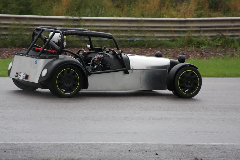
So here is an update on the engine build:

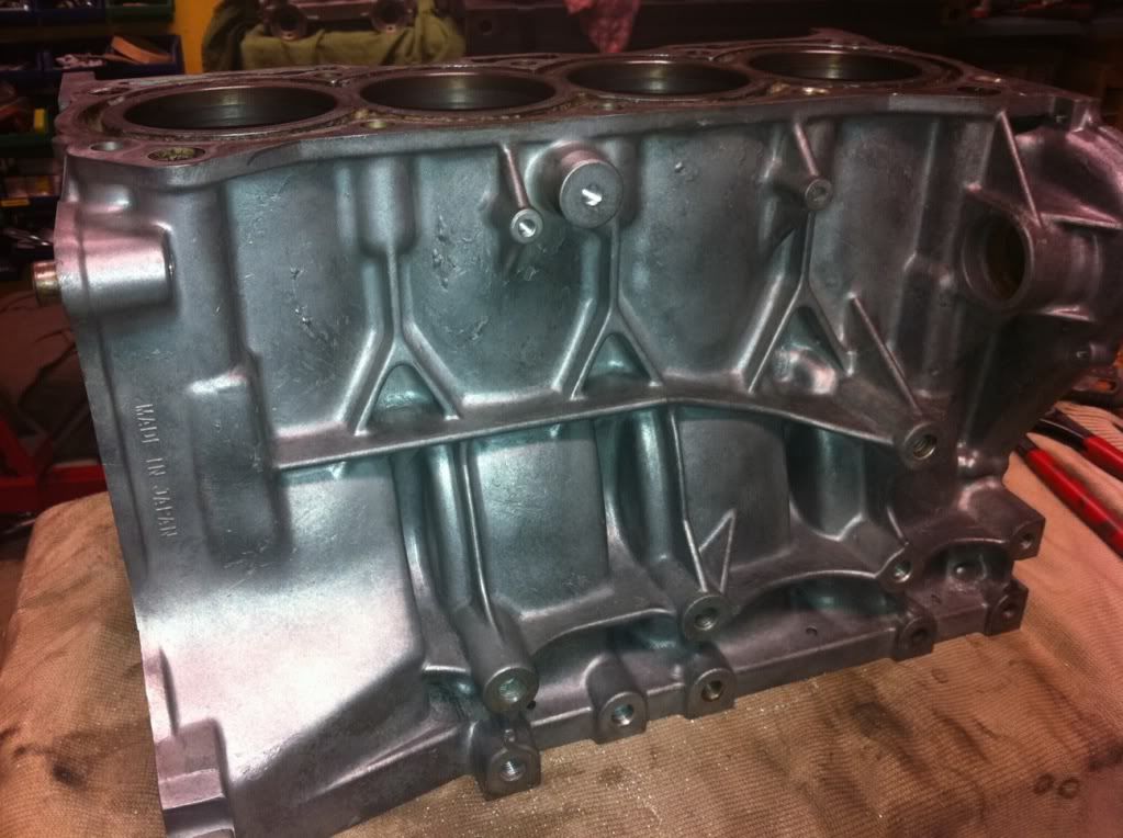
The aim for the new engine is about 200 reliable bhp. It is based on a G13B MKII block. Compression will be 8.6:1.

The block is O-ringed and partly grout filled
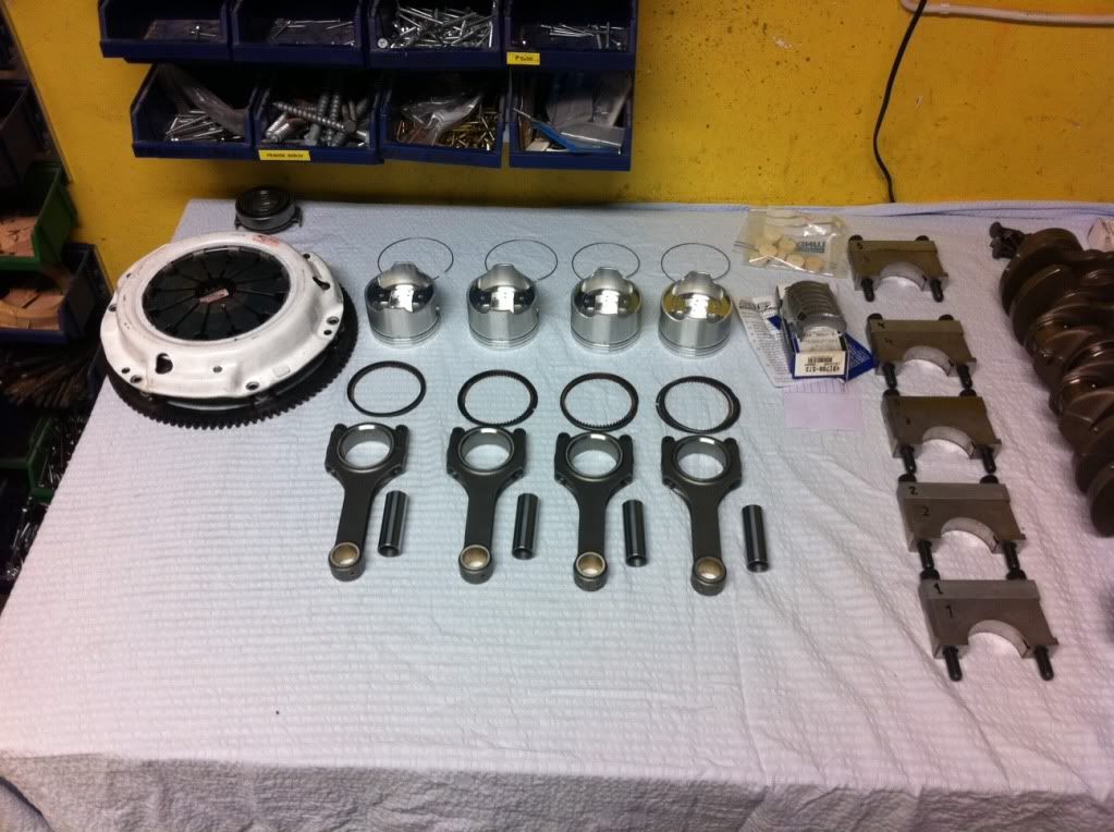
Forged pistons
H-profile rods
New bearings
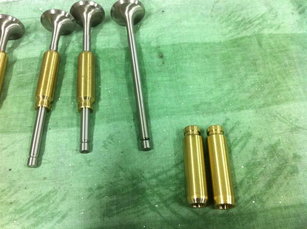
0.5mm oversize ss valves and bronze valve guides.
Cams are 200/335 (@ 0.050" lift)
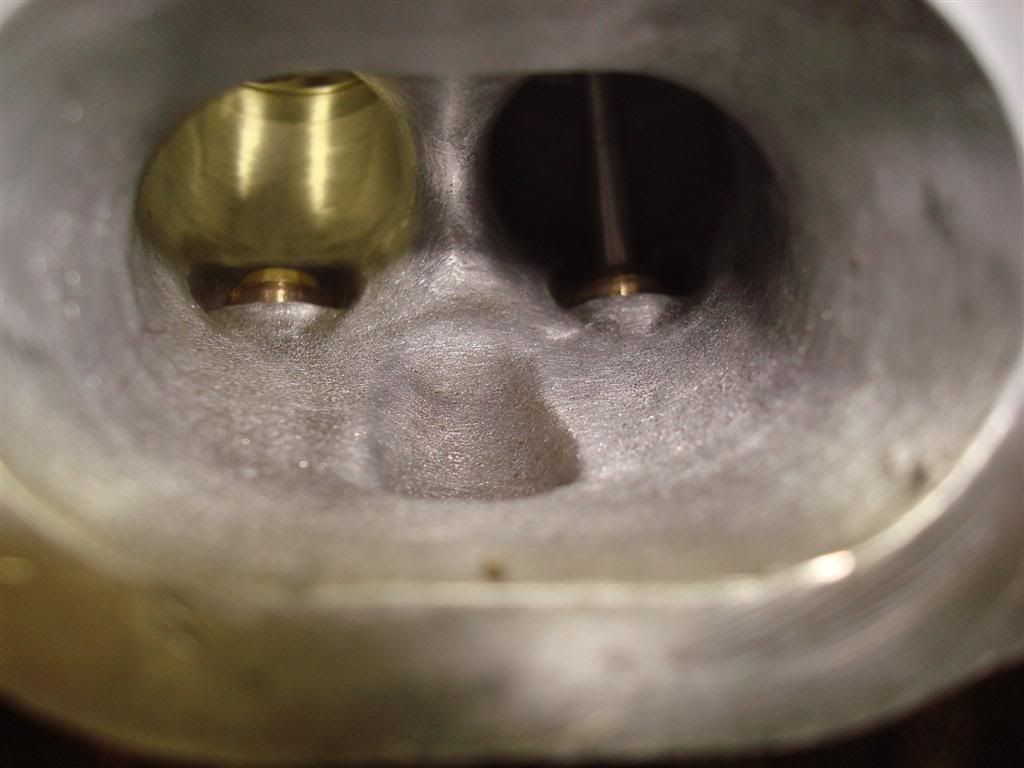
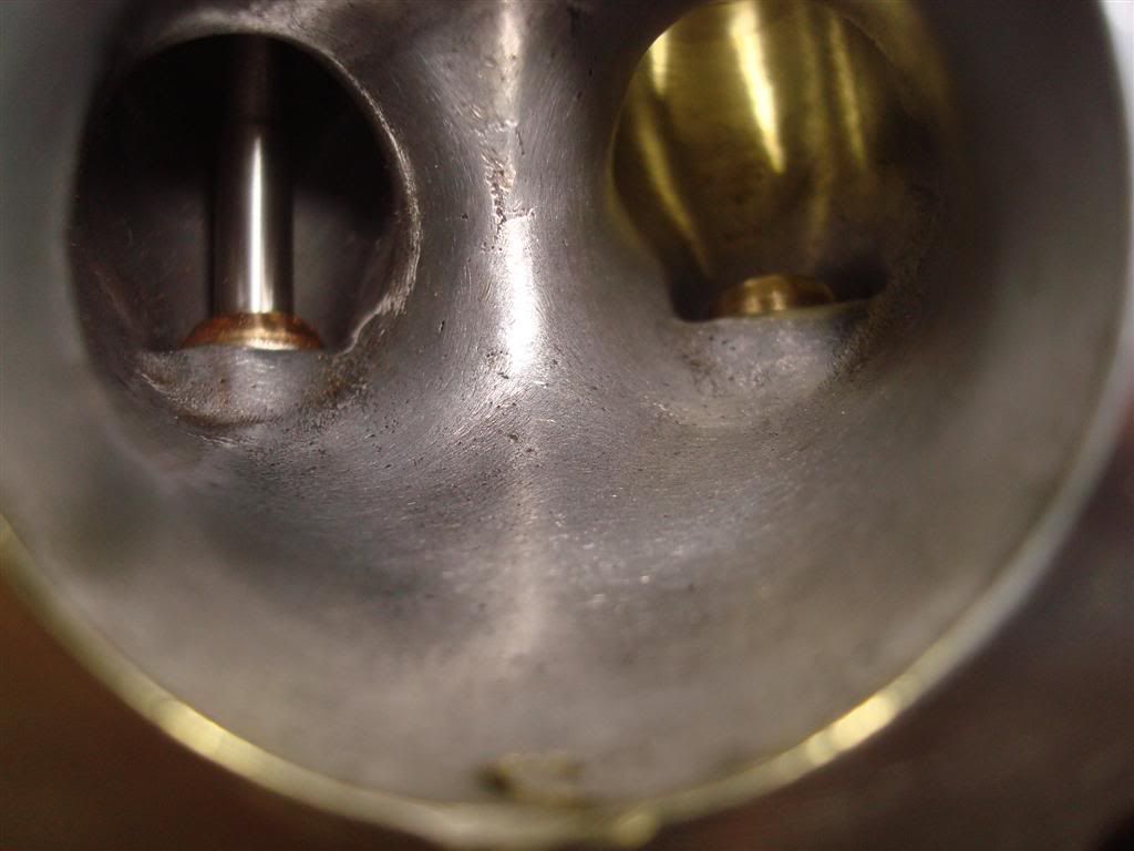
All sharp edges are removed from the combustion chambers.
Dry sump oil system using a two stage scavenge pump, and a Suzuki 1.6l oil-pump for pressure.
Turbo will be a TD04-14T vrom a Volvo S40 2.0

First out is the head:

Some work to the ports:
Image

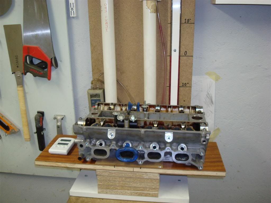
DIY built flow bench, borrowed from a friend. Surprisingly accurate results between measurements!
Image

Image

Image

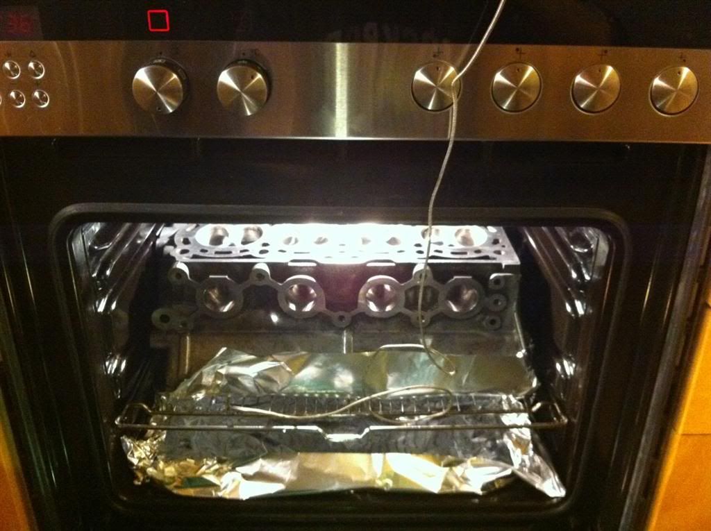
About to change valve guides. Don't tell my wife!
Image

Image

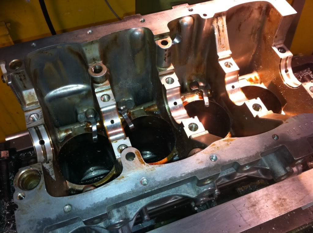
One clean MKII block:
Image

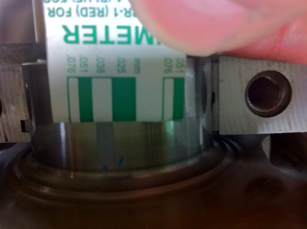
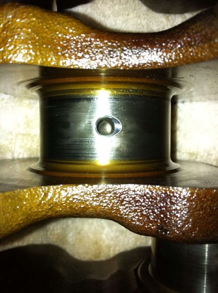
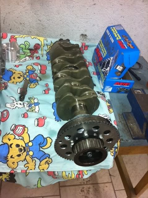
Crank has been checkad for straightness, and dimensions. Slight modification to oil holes:
Image

Image

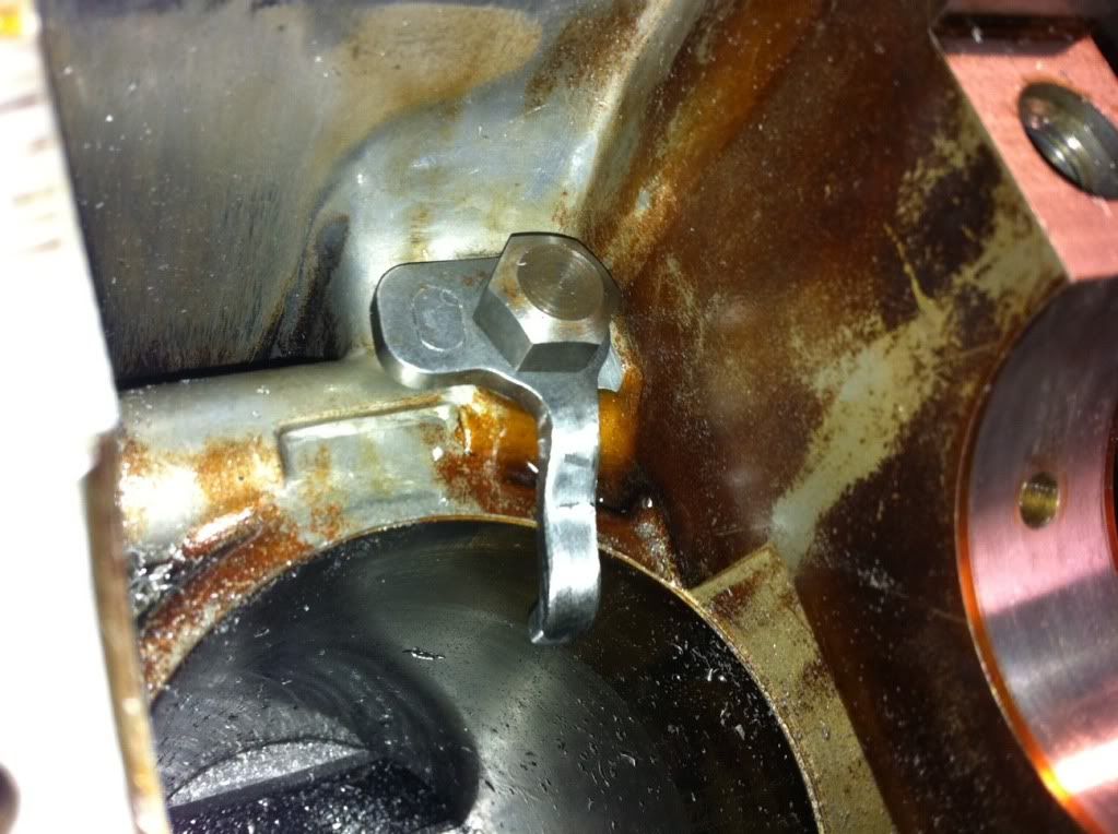
Modified the block for piston oil cooling jets:
Image

Image

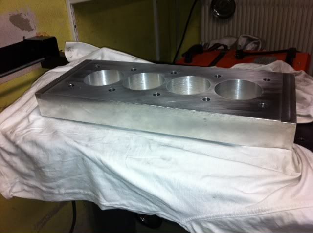
Torque plate for boring the block:
Image

Image

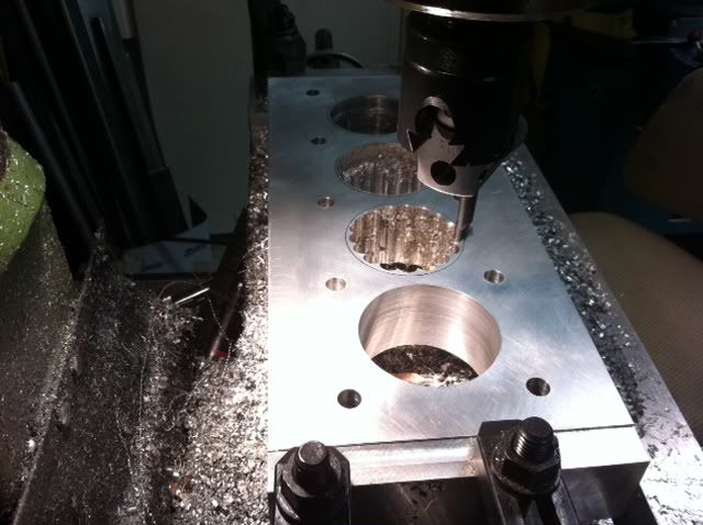
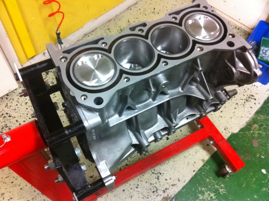
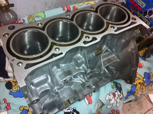
Block bored to 75mm skimmed and o-ringed:
Image

Crank, trigger wheel and drive pulley for the scavenge pump:
Image

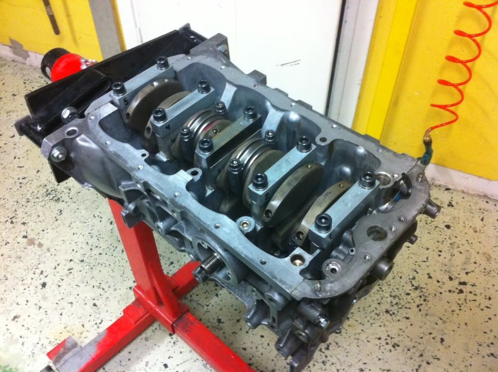
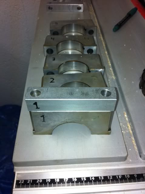
Reinforcement for the crank caps:
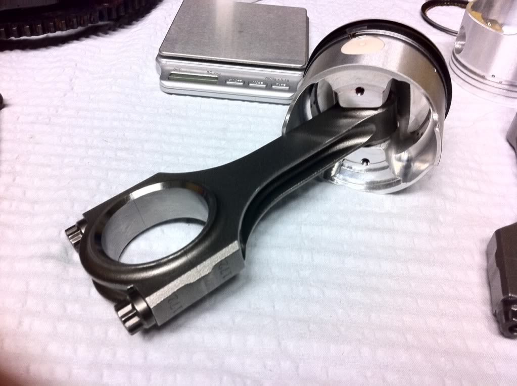
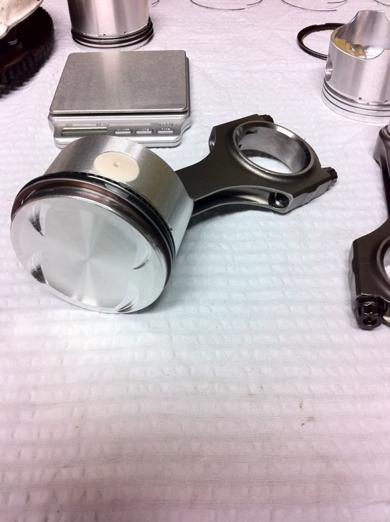
Image

Pistons and rods:
Image

Image

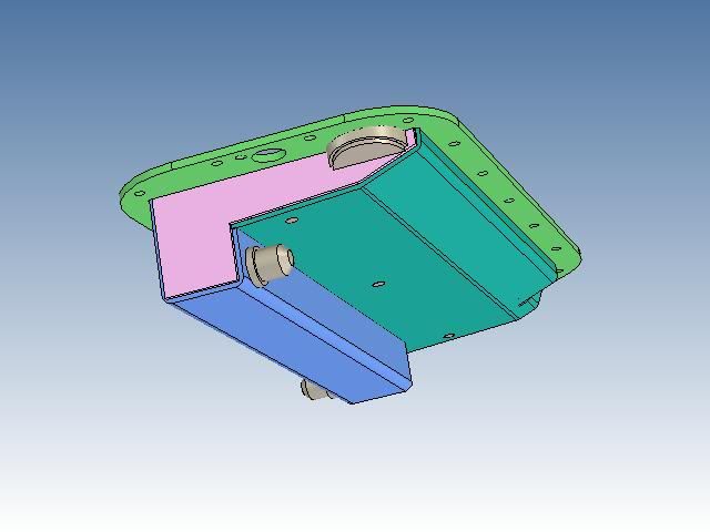
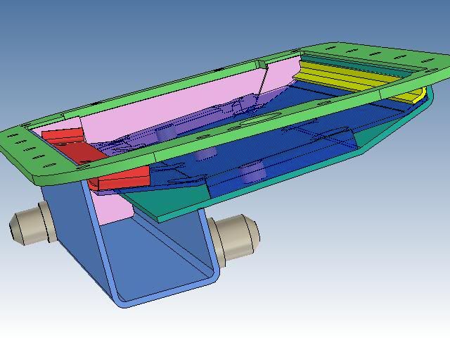
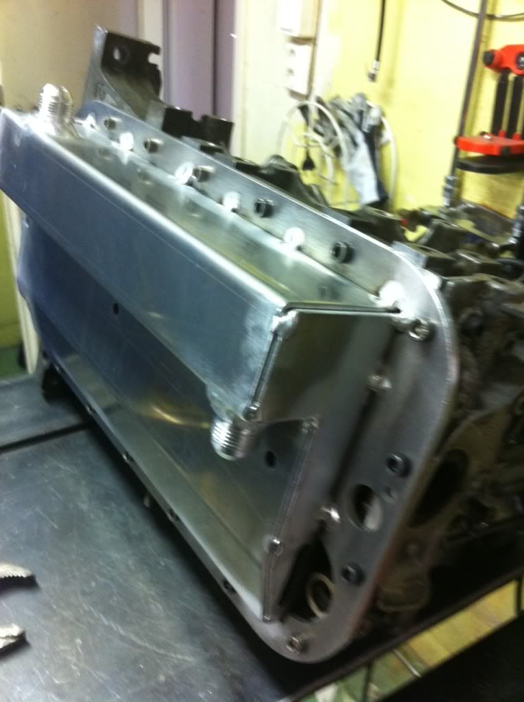
Drew a new oil tray for the dry sump system:
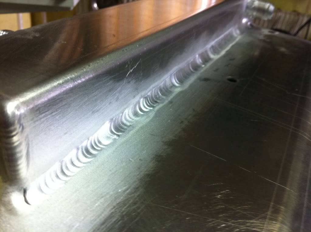
Image

Manufactured it:
Image

Image

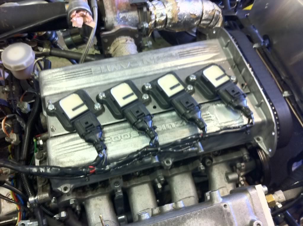
Will be reusing the VAG COPs from the old engine.
Image

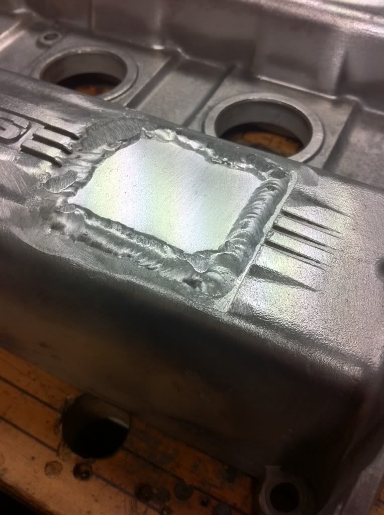
Welded the oil filler cap shut. I fill oil in the oil tank for the dry sump instead:
Image

Some stuff that might come in handy:
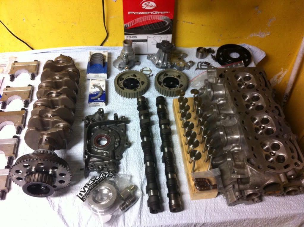
Image

Image

Bottom end built:
Image

Image


Top
 Profile  
 
PostPosted: Thu May 19, 2011 5:06 pm 
Offline
User avatar

Joined: Fri Nov 28, 2003 4:21 pm
Posts: 593
Location: Durham, UK
Hi Pete,

I like what you are doing with your engine.
I'm in the process of making dry sump after making CAD but you already have it.
Do you think you can send me your CAD file?
I will pm you my e-mail address!
Oh also, where did you get your con rods from?

I like your oil squirters. I'm getting a set from Juke 1.6 Turbo engine, soon.

Thanks in advance!

Atchi


Top
 Profile  
 
PostPosted: Fri May 20, 2011 11:50 am 
Offline
User avatar

Joined: Sat Mar 22, 2008 8:44 pm
Posts: 46
Here is the Oil Tray flange as a step file. Two of the holes at the rear of the engine are about 1mm off, but it can be corrected with a file in 30 seconds so it is not worth the effort of updating the cad file.

Note that the flange is for a dry sump tray so it has no hole to attach the oil pickup. It is also made for a G16 oil pump with a hole for a crank sensor. The crank sensor hole should be removed if a stock G13B oil pump is used.

BR Peter

Attachment:
Suz_G13B_5mm_OilTrayFlange.zip [15.36 KIB]
Downloaded 328 times


Top
 Profile  
 
PostPosted: Fri May 20, 2011 4:02 pm 
Offline
Suzuki Elder
User avatar

Joined: Mon Dec 01, 2003 12:47 pm
Posts: 11675
Location: columbus, ohio
hi peter,

i really like your dry sump.

is there another weldment to cover the oil pump over-pressure discharge? it doesn't appear on the cad or pic and i'm interested to see what you're doing at that spot.

_________________
1991 Blue Geo Metro Convertible highly modified 1.0L Turbo3 5 spd. - 1991 Red Geo Metro Convertible customized with a Twincam 5 spd.

My Turbo3 Project
My Cardomain Page -Ol' Blue
My YouTube Channel
My Photo Gallery
SAAB Sonett II


Top
 Profile  
 
PostPosted: Fri May 20, 2011 4:50 pm 
Offline
User avatar

Joined: Sat Mar 22, 2008 8:44 pm
Posts: 46
I am using the engine oil pump for pressure fed from an oil tank. Kind of a low budget dry sump not to have an external pressure pump, but on the other hand the original pump is dimensioned for this engine and if it is fed oil from a tank it will not suck air and thus, work just as well or maybe better than an external one.

On the oil-in side the passage from the oil pickup is blocked and oil is fed from an oil tank to the threaded bung at the side of the pump.

On the oil-out side everything looks like stock. Overpressure valve returns the oil to the sump. It is free to flow inside the pan. The hole where the overpressure spring and small piston is placed is not where the return oil is coming from, but I added a small "cup" on the underside for any oil coming from there anyway to return to the sump, besides the air needs to be able to enter for the piston within the valve to be able to move.

Can be seen on this cad picture:

Image

There is also a two stage scavenge pump driven off the crank that evacuates oil from the tray and pumps it into the oil tank. This is described earlier in the thread.

/Peter


Top
 Profile  
 
Display posts from previous:  Sort by  
Post new topic Reply to topic  [ 72 posts ]  Go to page Previous  1, 2, 3  Next

All times are UTC - 5 hours


Who is online

Users browsing this forum: No registered users and 2 guests


You cannot post new topics in this forum
You cannot reply to topics in this forum
You cannot edit your posts in this forum
You cannot delete your posts in this forum
You cannot post attachments in this forum

Search for:
Jump to:  
Powered by phpBB® Forum Software © phpBB Group